The web plate thickness is assumed to be 16 mm. An example with a plain plate welded to the top flange is presented in early editions of the Red Book2.
2
The moment-resisting capacities of plate girders lie somewhere between those of deep standard rolled wide-flange shapes and those of trusses.
. ASSUMPTIONS FOR THE DESIGN OF PLATE GIRDER BRIDGES Following assumptions are made in the design of plate girder bridges. Usually the flange and web plates are connected by welding Figure 71. Provisions highlighted in different codes of practice in designing plate girder bridges.
The flanges of plate girders resist the bending moment. The web height is taken as equal to 1200 mm which conforms to the recommended values L 7 9 12000 7 9 1429 1111 mm. The design of a plate girder element is the.
Formula 5 may seem too complicated for design purposes. For practicaluse this difficulty is overcome by tabulating allowable stresses for different materials ASTM A7 A36 etc and girder dimensionso An example is given as Table 1. ZAHN What differentiates a beam from a plate girder.
The use of welded plate girders for short to medium span highway bridges offers greatest flexibility in choosing the most economical section. What are the options. SITE-Blauvelt Engineers Pittsburgh PA.
For railway bridges the girder depth will usually be in the range L o 12 to L o 8 where L o is the length between points of zero moment. This document consists of a comprehensive steel girder bridge design example with instructional commentary based on the AASHTO LRFD Bridge Design Specifications Second Edition 1998 including interims for 1999 through 2002. A plate bracket made of 10mm thick plate is butt welded to the flange of a steel stanchion.
Box girder rolled girder and plate girder bridges are primarily flexural structures which carry their loads by bending between the supports. The cross girder is designed as a welded plate girder as shown in Figure 4175. Design of Plate Girders 91 INTRODUCTION The most common type of plate girder is an I-shaped section built up from two flange plates and one web plate as shown in Figs.
Important conceptual differences but not only are discussed. Design of the Cross Girder Cross Section. THREE-SPAN CONTINUOUS STRAIGHT COMPOSITE I GIRDER Load and Resistance Factor Design Third Edition -- Customary US.
Currently design of plate girders and weld-fabricated beams necessitates an iteration of trial designs to establish the web-buckling range used in analysis. 1The web plates of plate girders resist the shear force and the shear stress is uniformly distributed over entire cross sectional area of the web. Girders fabricated in this manner are known as welded plate girders and their depth to web thickness ratio dtw may be up to 400.
The main types of structural action are as follows. Work out Examples Design a Welded plate girder with a simply support span of 56 ft to support a uniform load of 3kipsft including girder self weight and two concentrated loads of 75 kips located 20 ft from each end. 14 RELEVANCY OF THE PROJECT.
The flange width is taken as equal. Pyw Design strength of web fyw γm γm Material safety factor for steel 115 The elastic critical stress Refer Table 1 of the previous chapter has been simplified and given based on ad and td as given in Table - 1. Plate Girder Design Using LRFD CYNTHIA J.
Gantry girders would have to be doubly symmetric or have the top flange fully restrained. An example is also presented. They offer the following advantages over the standard rolled sections 1.
Welded plate girders can be designed as long and as deep as required by the design and fabrication method. With these tables it 1s a simple matter to find the allowable shear stress for a given girder geometry or. 6 Common types of plate girder bridge Girder Design contd Girder Design contd The first step in the design of plate girder section is to select the value of the web depth D.
However it is a necessary and important part of plate girder design when applying the Load and Resistance Factor Design LRFD Specification1 A beam can be a rolled or a welded shape but it does not have. Times the nominal weld size. The design example and commentary are intended to serve as a guide to aid bridge design engineers with the implementation.
The following note discusses the standard formula for the shear flow between web and flanges of a doubly symmetric beam which is used for weld design and gives the background to the formula in Eurocode 3 Part 51. Size of weld 61907 884 mm. The bracket carriers a load of 100kN at the eccentricity of 110mm from the face of the stanchion.
By the end of this study the author will come out with the design example and the spreadsheet to ease the calculation of designing welded plate girder bridges for all codes being studied. The degree of continuity of the steel girders over their intermediate supports determines the structural action within the steel bridge. This paper presents the design procedures related to bending shear and in particular local buckling resistance of Steel Plate Girders according to the requirements of Eurocode 3 and Albanian National Design Code KTP-78.
Design the welds between the flange and web of a plate girder. Examples of flexible con-nections include framing angles top angles of seated beam connections and simple end plate connections. Hence provide 9mm size weld.
Up to 5 cash back In this situation girders are to be fabricated using flange and web plates as per requirement. The moment-resisting capacities of plate girders lie somewhere between those of deep standard rolled wide-flange shapes and those of trusses. Cranberry Township PA and Robert E.
This may seem to be a trivial question. Except where the ends of stiffeners are welded to the flange fillet welds joining transverse stiffeners to girder webs shall start or termi-. Because of higher dtw the buckling of.
Looking back at the BS 5950 examples in the SCI library most are mono-symmetric with a channel welded to the top flange. PLATE GIRDERS II where qe Elastic critical shear strength values to be used in design for different values of ad and dt are tabulated in Table - 1. At this aim a steel plate girder is analyzed.
Depending on the type of girder use Chapter B F and Chapter G accordingly. Bridge Software Development International Ltd. Design and Optimization of Plate Girders and Weld-fabricated Beams for Building Construction Engineering Journal American Institute of Steel Construction Vol.
Design of Plate Girders 91 INTRODUCTION The most common type of plate girder is an I-shaped section built up from two flange plates and one web plate as shown in Figs. Units by Michael A. Let is assume that the butt weld will have complete penetration.
2
2
Lrfd Steel Girder Superstructure Design Example Lrfd Structures Bridges Structures Federal Highway Administration

Welded Plate An Overview Sciencedirect Topics
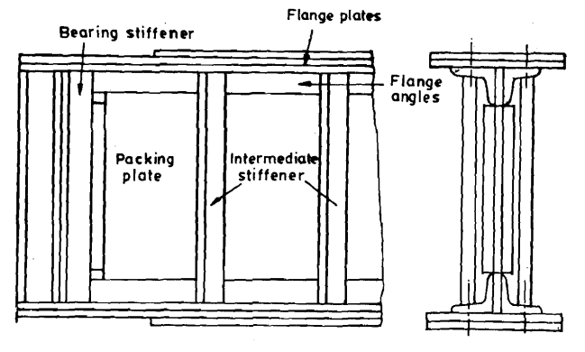
Plate Girder Structural Guide

Plate Girder Bridges An Overview Sciencedirect Topics
2

Pdf Design Of Plate Girders Mik Wanul Khosiin Academia Edu
0 comments
Post a Comment